

PCA9554 I/O Expander
The PCA9554 component allows you to use a variety of I/O expanders in ESPHome that use the I²C Bus for communication. Once configured, you can use any of the IO pins (up to 16) with your projects. Within ESPHome they emulate a real internal GPIO pin and can therefore be used with many of ESPHome’s components such as the GPIO binary sensor or GPIO switch. Any option accepting a Pin Schema can theoretically be used, but some more complicated components that do communication through this I/O expander will not work.
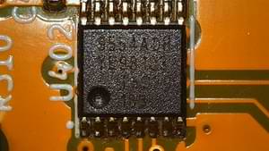
Supported Devices
Section titled “Supported Devices”Set device: to the part in use. The PCAL parts add pull resistors, input latching and a selectable output
drive strength on top of the plain I/O. At startup every PCAL pin is set as an input with its pull resistors
disconnected, whatever the chip’s power-on state, before the configured pin modes are applied.
| Device | Number of Pins | I²C Address | Features |
|---|---|---|---|
| PCA9536 | 4 | 0x41 | I/O |
| PCA9534 | 8 | 0x20-0x27 | I/O |
| PCA9534A | 8 | 0x38-0x3F | I/O |
| PCA9538 | 8 | 0x70-0x73 | I/O |
| PCA9554 | 8 | 0x20-0x27 | I/O |
| PCA9554A | 8 | 0x38-0x3F | I/O |
| TCA9554 | 8 | 0x20-0x27 | I/O |
| PCA9535 | 16 | 0x20-0x27 | I/O |
| PCA9555 | 16 | 0x20-0x27 | I/O |
| TCA9535 | 16 | 0x20-0x27 | I/O |
| TCA9555 | 16 | 0x20-0x27 | I/O |
| PCAL9538 | 8 | 0x70-0x73 | I/O, pull up/down, latching, drive strength |
| PCAL9555 | 16 | 0x20-0x27 | I/O, pull up/down, latching, drive strength |
Devices that show a range of I²C addresses have an address that can be set using strapping pins on the device.
Other expanders with the same register layout work when configured as the device with the same number of pins
and features; set address: to match the part.
# Example configuration entrypca9554:  - id: pca9554_hub    device: PCA9554
# Individual outputsswitch:  - platform: gpio    name: "PCA9554 Pin 2"    pin:      pca9554: pca9554_hub      number: 2      mode:        output: true
# Individual inputsbinary_sensor:  - platform: gpio    name: "PCA9554 Pin 3"    pin:      pca9554: pca9554_hub      number: 3      mode:        input: true
Configuration Variables
Section titled “Configuration Variables”- id (Required, ID): The id to use for this
pca9554component. - address (Optional, int): The I²C address of the device; see the table above. Defaults to the lowest
address of the selected
device, with all address pins low:0x20for most parts,0x38for the PCA9534A and PCA9554A,0x41for the PCA9536 and0x70for the PCA9538 and PCAL9538. - device (Optional, string): The part in use, one of the names in the table above. Defaults to
PCA9554, or to the plain part with the pins given bypin_count. - pin_count (Optional, int): The number of pins of the expander,
4,8or16, for configurations that predatedevice. Withdeviceset it may be left out; if both are given they must agree. - interrupt_pin (Optional, Pin Schema): The pin connected to the INT output of the expander. When configured, the component becomes interrupt-driven instead of polling: it only reads the chip when a pin actually changes state, significantly reducing I²C bus traffic and CPU usage. The INT pin is active-low and open-drain, so an external or internal pull-up resistor is required. Must be an internal GPIO pin (not another expander pin). On the PCAL parts every input pin asserts INT and every output pin is masked, so no per-pin setup is needed.
Pin Configuration Variables
Section titled “Pin Configuration Variables”- pca9554 (Required, ID): The id of the
pca9554component of the pin. Instead of an id, anaddress:can be given to select the hub by its I²C address; see Selecting an I2C Expander by Address. - number (Required, int): The pin number.
- inverted (Optional, boolean): If all read and written values
should be treated as inverted. Defaults to
false. - mode (Optional, boolean(s)): Pin mode settings for the selected pin. Multiple pin modes may be selected by
indenting them after the
mode:entry in the YAML as shown in the example above. All devices supportinputandoutput. The PCAL parts additionally supportpullupandpulldown; the plain parts reject them. - latch (Optional, boolean): PCAL parts only. Latch an
inputpin, see below. Defaults tofalse. - drive_strength (Optional, percentage): PCAL parts only. The drive strength of an
outputpin, one of25%,50%,75%or100%. Refer to the datasheet of your device for the recommended value. Defaults to100%; the plain parts reject this option.
NOTE
Pin numbers start at 0. Datasheets for 16-pin parts may split the pins into two ports (P0_0..P0_7 and
P1_0..P1_7). Port 0 is pins 0-7 and port 1 is pins 8-15, so P0_4 is pin 4 and P1_4 is pin 12.
Description of the Mode Settings
Section titled “Description of the Mode Settings”input:
Configure the pin as a high impedance input.
output:
Configure the pin as a push/pull output.
pullup:
If the pin is configured as an input enable a 100K pull up.
pulldown:
If the pin is configured as an input enable a 100K pull down.
Latched Inputs
Section titled “Latched Inputs”With latch: true a PCAL part holds a changed input level until the component reads the input register, which
happens on every poll or, with interrupt_pin, when INT fires. INT stays asserted until that read. A pulse
shorter than the poll interval is therefore still reported once instead of being missed; the level read back is
the latched one, even if the pin has already returned to its original state.
PCAL Example
Section titled “PCAL Example”pca9554: - id: pcal9538_hub device: PCAL9538
switch: - platform: gpio name: "PCAL9538 Pin 2" pin: pca9554: pcal9538_hub number: 2 drive_strength: 50% mode: output: true
binary_sensor: - platform: gpio name: "PCAL9538 Pin 3" pin: pca9554: pcal9538_hub number: 3 latch: true mode: input: true pullup: true