MAX31865 Platinum RTD Temperature Sensor
The max31865 temperature sensor allows you to use your max31865 RTD
temperature sensor (datasheet) with ESPHome
As the communication with the MAX31865 is done using SPI, you need to have an spi bus in your configuration with both miso_pin and mosi_pin set.
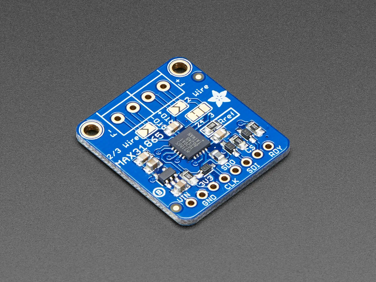
VINconnects to 5V (3V3will output 3.3V), or directly connect3V3to 3.3V3Vois not used by ESPHomeGNDconnects to groundCLKconnects to the SPI clk_pinSDOconnects to the SPI miso_pinSDIconnects to the SPI mosi_pinCSconnects to a free GPIO pinRDYis not used by ESPHome
# Example configuration entryspi:  miso_pin: D0  mosi_pin: D1  clk_pin: D2
sensor:  - platform: max31865    name: "Living Room Temperature"    cs_pin: D3    reference_resistance: 430 Ω    rtd_nominal_resistance: 100 Ω
Configuration variables
Section titled “Configuration variables”- cs_pin (Required, Pin Schema): The Chip Select pin of the SPI interface.
- update_interval (Optional, Time): The interval to check the sensor. Defaults to
60s. - reference_resistance (Required, float): Reference resistor on the PCB. Adafruit’s PT100 (#3328) uses 430 Ω, their PT1000 (#3648) uses 4300 Ω.
- rtd_nominal_resistance (Required, float): Nominal resistance of the RTD at 0°C. PT100 is 100 Ω, PT1000 is 1000 Ω.
- mains_filter (Optional, string): The mains power frequency to reject (
50 Hzor60 Hz). Defaults to60 Hz. - rtd_wires (Optional, int): The number of RTD wires. Be sure to solder board jumpers to match! Defaults to
4. - spi_id (Optional, ID): Manually specify the ID of the SPI Component if you want to use multiple SPI buses.
- All other options from Sensor.