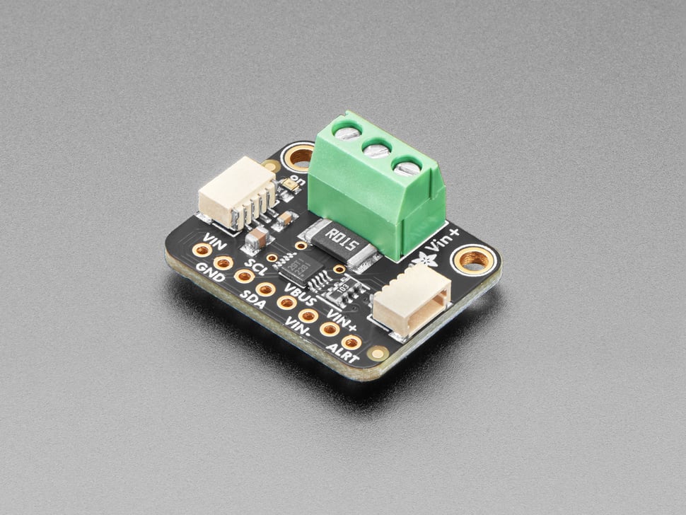
INA2xx family of digital power monitors

Supported devices
The ina2xx sensor platform allows you to use family of Texas Instruments current and power
sensors with ESPHome. Appropriate interface (I²C Bus or SPI Bus) is
requred to be set up in your configuration for this sensor to work.
| Product | Protocol | Description |
|---|---|---|
| INA228 | I²C 8 | 5-V, 20-Bit, Ultra-Precise Power/Energy/Charge Monitor |
| INA229 | SPI 8 | 5-V, 20-Bit, Ultra-Precise Power/Energy/Charge Monitor |
| INA238 | I²C 8 | 5-V, 16-Bit, High-Precision Power Monitor |
| INA239 | SPI 8 | 5-V, 16-Bit, High-Precision Power Monitor |
| INA237 | I²C 8 | 5-V, 16-Bit, Precision Power Monitor |
All devices can measure a selectable full-scale differential input of ±163.84 mV or ±40.96 mV across the shunt with common-mode voltage support from –0.3 V to +85 V.
INA228 and INA229 are the most comprehensive devices of the family with extra features: 20-bit ADC resolution, energy and charge accumulation, and capability to utilize the temperature measurement to compensate for shunt resistor temperature variance.
Over I²C
Use ina2xx_i2c component to connect INA228, INA237, or INA238 device over I²C bus.
# Example configuration entry for I²C
sensor:
  - platform: ina2xx_i2c
    id: my_charge_sensor
    model: INA228
    address: 0x40
    shunt_resistance: 0.010 ohm
    max_current: 10 A
    adc_range: 0
    update_interval: 60s
    current: "INA228 Current"
    bus_voltage: "INA228 Bus Voltage"
    charge: "INA228 Charge"
Configuration variables
model (Required, string): The model of the INA2xx sensor. Options are
INA228,INA237,INA238.address (Optional, int): Manually specify the I²C address of the sensor. Defaults to
0x40.shunt_resistance (Required, float): The value of the shunt resistor used for current calculation. No default value.
max_current (Required, float): The maximum current you are expecting. Component will use it to calibrate the sensor. No default value.
adc_range (Optional,
0or1): Selects the range for differential input across shunt resistor.0for ±163.84 mV,1for ±40.96 mV range. Defaults to0.adc_time (Optional, Time): The time in microseconds to perform a single ADC conversion. Defaults to
4120 us. Valid values are50 us,84 us,150 us,280 us,540 us,1052 us,2074 us,4120 us.Instead of one time for all ADC measurements, separate configuration of conversion times for shunt voltage, bus voltage, and temperature measurements possible. Options are the same as for
adc_time.adc_averaging (Optional, integer): Selects ADC sample averaging count. Defaults to
128. Valid values are1,4,16,64,128,256,512,1024.temperature_coefficient (Optional, integer from
0to16383): Temperature coefficient (ppm/°C) of the shunt for temperature compensation correction. Only applicable to INA228 and INA229 devices. Zero value means no compensation is done. Defaults to0.update_interval (Optional, Time): The interval to check the sensor. Defaults to
60s.reset_on_boot (Optional, boolean): Whether or not to reset the device configuration (including counters) on component initialization. Defaults to
true; setfalseto preserve counters through ESPHome resets.All other options from Sensor and I²C device.
Over SPI
Use ina2xx_spi component to connect INA229 or INA239 device over SPI bus.
# Example configuration entry for SPI
sensor:
  - platform: ina2xx_spi
    cs_pin: GPIOXX
    model: INA239
    shunt_resistance: 0.001130 ohm
    max_current: 40 A
    adc_range: 0
    temperature_coefficient: 50
    current: "INA239 Current"
    power: "INA239 Power"
Configuration variables
model (Required, string): The model of the INA2xx sensor. Options are
INA229,INA239.cs_pin (Required, Pin Schema): The Chip Select (CS) pin.
shunt_resistance (Required, float): The value of the shunt resistor used for current calculation. No default value.
max_current (Required, float): The maximum current you are expecting. Component will use it to calibrate the sensor. No default value.
adc_range (Optional,
0or1): Selects the range for differential input across shunt resistor.0for ±163.84 mV,1for ±40.96 mV range. Defaults to0.adc_time (Optional, Time): The time in microseconds to perform a single ADC conversion. Defaults to
4120 us. Valid values are50 us,84 us,150 us,280 us,540 us,1052 us,2074 us,4120 us.Instead of one time for all ADC measurements, separate configuration of conversion times for shunt voltage, bus voltage, and temperature measurements possible. Options are the same as for
adc_time.adc_averaging (Optional, integer): Selects ADC sample averaging count. Defaults to
128. Valid values are1,4,16,64,128,256,512,1024.temperature_coefficient (Optional, integer from
0to16383): Temperature coefficient (ppm/°C) of the shunt for temperature compensation correction. Only applicable to INA228 and INA229 devices. Zero value means no compensation is done. Defaults to0.update_interval (Optional, Time): The interval to check the sensor. Defaults to
60s.reset_on_boot (Optional, boolean): Whether or not to reset the device configuration (including counters) on component initialization. Defaults to
true; setfalseto preserve counters through ESPHome resets.All other options from Sensor and SPI device.
Sensors
The component offers nine sensors. You can configure all or any subset of the sensors. Each configured sensor
is reported separately on each update_interval. The name option is required for each sensor configured;
all other options from Sensor are also supported. Shorthand notation can be used for the sensors like this:
current: "Current".
- current (Optional): Calculated current output, A
- power (Optional): Calculated power output, always positive, W
- shunt_voltage (Optional): Differential voltage measured across the shunt, mV
- bus_voltage (Optional): Bus voltage output, V
- temperature (Optional): Internal die temperature measurement, °C
- energy (Optional): Calculated energy output, Wh (INA228/229 only)
- energy_joules (Optional): Calculated energy output, Joules (INA228/229 only)
- charge (Optional): Calculated charge output, Ah (INA228/229 only)
- charge_coulombs (Optional): Calculated charge output, Coulombs (INA228/229 only)
Lambda calls
The component exposes one function to reset INA228/INA229 energy and charge accumulators.
reset_energy_counters()
    // Within lambda, reset counters.
    id(my_charge_sensor).reset_energy_counters();
To simplify the use of this function, you can use the following example to add a button to reset the counters.
    button:
      - platform: template
        name: "Reset counters"
        on_press:
          - lambda: "id(my_change_sensor).reset_energy_counters();"
