DSMR Component
Component/Hub
Section titled “Component/Hub”The DSMR component connects to Dutch Smart Meters which comply to DSMR (Dutch Smart Meter Requirements), also known as ‘Slimme meter’ or ‘P1 port’.
This component supports plain non encrypted telegrams and also encrypted as used in Luxembourg. In case your equipment has encryption you must get a 32 character long encryption key from your energy company.
This component is passive, it does not transmit any data to your equipment, the equipment always transmits data which this component decodes and updates the configured sensors at the pace the data is received.
- For official information about DSMR refer to: DSMR Document
- For official information about the P1 port refer to: P1 Companion Standard
# Example configuration entryuart:  rx_pin: GPIO16  baud_rate: 115200  rx_buffer_size: 1700
dsmr:  # Optional. The ID of the DSMR. Specify it if you have multiple DSMR components.  id: dsmr_id
  # Optional. The ID of the UART hub.  # Required if you have multiple UARTs configured.  uart_id: uart_dsmr
  # Optional. 32 character long encryption key.  # Specify only if your smart meter uses encryption (f.e. if you have "Luxembourg Smarty")  decryption_key: !secret decryption_key
  # Optional. The id of the gas meter. Default=1.  gas_mbus_id: 1
  # Optional. The id of the water meter. Default=2.  water_mbus_id: 2
  # Optional. Specifies if the CRC check must be done. Default=true.  # You must set it to false for older DSMR versions because they do not provide a CRC.  crc_check: true
  # Optional. The size of the buffer used for reading DSMR telegrams.  # Specify this parameter only if your smart meter sends large telegrams.  max_telegram_length: 1500
  # Optional. P1 port's data request pin.  # DSMR module uses this pin to tell the smart meter when to send data.  # By default, smart meters send data continuously.  # Specifying this pin is only useful if you want to use a custom `request_interval`.  request_pin: GPIO5
  # Optional. The minimum time between two telegram readings. Default=0ms.  # The pace at which the smart meter sends its data determines the update frequency.  # This works best in combination with a `request_pin`, but this option will work without one, too.  request_interval: 0ms
  # Optional. The timeout on incoming data while reading a telegram. Default=200ms.  # When no new data arrives within the given timeout, the device will consider the current  # telegram a loss and starts looking for the header of the next telegram.  receive_timeout: 200ms
## List of available sensors and text sensors.# Not all sensors are available on all devices.#
sensor:  - platform: dsmr
    energy_delivered_lux:      name: "Energy Consumed Luxembourg. OBIS: 1-0:1.8.0"    energy_delivered_tariff1:      name: "Energy Consumed Tariff 1. OBIS: 1-0:1.8.1"    energy_delivered_tariff2:      name: "Energy Consumed Tariff 2. OBIS: 1-0:1.8.2"    energy_delivered_tariff3:      name: "Energy Consumed Tariff 3. OBIS: 1-0:1.8.3"    energy_delivered_tariff4:      name: "Energy Consumed Tariff 4. OBIS: 1-0:1.8.4"    energy_returned_lux:      name: "Energy Produced Luxembourg. OBIS: 1-0:2.8.0"    energy_returned_tariff1:      name: "Energy Produced Tariff 1. OBIS: 1-0:2.8.1"    energy_returned_tariff2:      name: "Energy Produced Tariff 2. OBIS: 1-0:2.8.2"    energy_returned_tariff3:      name: "Energy Produced Tariff 3. OBIS: 1-0:2.8.3"    energy_returned_tariff4:      name: "Energy Produced Tariff 4. OBIS: 1-0:2.8.4"    energy_delivered_tariff1_ch:      name: "Energy Consumed Tariff 1 (CH). OBIS: 1-1:1.8.1"    energy_delivered_tariff2_ch:      name: "Energy Consumed Tariff 2 (CH). OBIS: 1-1:1.8.2"    energy_returned_tariff1_ch:      name: "Energy Produced Tariff 1 (CH). OBIS: 1-1:2.8.1"    energy_returned_tariff2_ch:      name: "Energy Produced Tariff 2 (CH). OBIS: 1-1:2.8.2"    total_imported_energy:      name: "Reactive Energy Imported (Total). OBIS: 1-0:3.8.0"    reactive_energy_delivered_tariff1:      name: "Reactive Energy Imported Tariff 1. OBIS: 1-0:3.8.1"    reactive_energy_delivered_tariff2:      name: "Reactive Energy Imported Tariff 2. OBIS: 1-0:3.8.2"    reactive_energy_delivered_tariff3:      name: "Reactive Energy Imported Tariff 3. OBIS: 1-0:3.8.3"    reactive_energy_delivered_tariff4:      name: "Reactive Energy Imported Tariff 4. OBIS: 1-0:3.8.4"    total_exported_energy:      name: "Reactive Energy Exported (Total). OBIS: 1-0:4.8.0"    reactive_energy_returned_tariff1:      name: "Reactive Energy Exported Tariff 1. OBIS: 1-0:4.8.1"    reactive_energy_returned_tariff2:      name: "Reactive Energy Exported Tariff 2. OBIS: 1-0:4.8.2"    reactive_energy_returned_tariff3:      name: "Reactive Energy Exported Tariff 3. OBIS: 1-0:4.8.3"    reactive_energy_returned_tariff4:      name: "Reactive Energy Exported Tariff 4. OBIS: 1-0:4.8.4"    power_delivered:      name: "Power Consumed. OBIS: 1-0:1.7.0"    power_returned:      name: "Power Produced. OBIS: 1-0:2.7.0"    power_delivered_ch:      name: "Power Consumed (CH). OBIS: 1-1:1.7.0"    power_returned_ch:      name: "Power Produced (CH). OBIS: 1-1:2.7.0"    reactive_power_delivered:      name: "Reactive Power Imported. OBIS: 1-0:3.7.0"    reactive_power_returned:      name: "Reactive Power Exported. OBIS: 1-0:4.7.0"    electricity_threshold:      name: "Electricity Threshold. OBIS: 0-0:17.0.0"    electricity_switch_position:      name: "Electricity Switch Position. OBIS: 0-0:96.3.10"    electricity_failures:      name: "Electricity Failures. OBIS: 0-0:96.7.21"    electricity_long_failures:      name: "Long Electricity Failures. OBIS: 0-0:96.7.9"    electricity_sags_l1:      name: "Voltage Sags L1. OBIS: 1-0:32.32.0"    electricity_sags_l2:      name: "Voltage Sags L2. OBIS: 1-0:52.32.0"    electricity_sags_l3:      name: "Voltage Sags L3. OBIS: 1-0:72.32.0"    electricity_swells_l1:      name: "Voltage Swells L1. OBIS: 1-0:32.36.0"    electricity_swells_l2:      name: "Voltage Swells L2. OBIS: 1-0:52.36.0"    electricity_swells_l3:      name: "Voltage Swells L3. OBIS: 1-0:72.36.0"    voltage_sag_time_l1:      name: "Voltage Sag Time L1. OBIS: 1-0:32.33.0"    voltage_sag_time_l2:      name: "Voltage Sag Time L2. OBIS: 1-0:52.33.0"    voltage_sag_time_l3:      name: "Voltage Sag Time L3. OBIS: 1-0:72.33.0"    voltage_sag_l1:      name: "Voltage Sag L1. OBIS: 1-0:32.34.0"    voltage_sag_l2:      name: "Voltage Sag L2. OBIS: 1-0:52.34.0"    voltage_sag_l3:      name: "Voltage Sag L3. OBIS: 1-0:72.34.0"    voltage_swell_time_l1:      name: "Voltage Swell Time L1. OBIS: 1-0:32.37.0"    voltage_swell_time_l2:      name: "Voltage Swell Time L2. OBIS: 1-0:52.37.0"    voltage_swell_time_l3:      name: "Voltage Swell Time L3. OBIS: 1-0:72.37.0"    voltage_swell_l1:      name: "Voltage Swell L1. OBIS: 1-0:32.38.0"    voltage_swell_l2:      name: "Voltage Swell L2. OBIS: 1-0:52.38.0"    voltage_swell_l3:      name: "Voltage Swell L3. OBIS: 1-0:72.38.0"    current_l1:      name: "Current Phase 1. OBIS: 1-0:31.7.0"    current_l2:      name: "Current Phase 2. OBIS: 1-0:51.7.0"    current_l3:      name: "Current Phase 3. OBIS: 1-0:71.7.0"    current:      name: "Current. OBIS: 1-0:11.7.0"    current_n:      name: "Neutral Current. OBIS: 1-0:91.7.0"    current_sum:      name: "Current Sum. OBIS: 1-0:90.7.0"    current_fuse_l1:      name: "Current Fuse Phase 1. OBIS: 1-0:31.4.0"    current_fuse_l2:      name: "Current Fuse Phase 2. OBIS: 1-0:51.4.0"    current_fuse_l3:      name: "Current Fuse Phase 3. OBIS: 1-0:71.4.0"    power_delivered_l1:      name: "Power Consumed Phase 1. OBIS: 1-0:21.7.0"    power_delivered_l2:      name: "Power Consumed Phase 2. OBIS: 1-0:41.7.0"    power_delivered_l3:      name: "Power Consumed Phase 3. OBIS: 1-0:61.7.0"    power_returned_l1:      name: "Power Produced Phase 1. OBIS: 1-0:22.7.0"    power_returned_l2:      name: "Power Produced Phase 2. OBIS: 1-0:42.7.0"    power_returned_l3:      name: "Power Produced Phase 3. OBIS: 1-0:62.7.0"    reactive_power_delivered_l1:      name: "Reactive Power Imported L1. OBIS: 1-0:23.7.0"    reactive_power_delivered_l2:      name: "Reactive Power Imported L2. OBIS: 1-0:43.7.0"    reactive_power_delivered_l3:      name: "Reactive Power Imported L3. OBIS: 1-0:63.7.0"    reactive_power_returned_l1:      name: "Reactive Power Exported L1. OBIS: 1-0:24.7.0"    reactive_power_returned_l2:      name: "Reactive Power Exported L2. OBIS: 1-0:44.7.0"    reactive_power_returned_l3:      name: "Reactive Power Exported L3. OBIS: 1-0:64.7.0"    voltage_l1:      name: "Voltage Phase 1. OBIS: 1-0:32.7.0"    voltage_l2:      name: "Voltage Phase 2. OBIS: 1-0:52.7.0"    voltage_l3:      name: "Voltage Phase 3. OBIS: 1-0:72.7.0"    voltage_avg_l1:      name: "Voltage Avg Phase 1. OBIS: 1-0:32.24.0"    voltage_avg_l2:      name: "Voltage Avg Phase 2. OBIS: 1-0:52.24.0"    voltage_avg_l3:      name: "Voltage Avg Phase 3. OBIS: 1-0:72.24.0"    voltage:      name: "Voltage (Overall). OBIS: 1-0:12.7.0"    frequency:      name: "Grid Frequency. OBIS: 1-0:14.7.0"    abs_power:      name: "Absolute active instantaneous power. OBIS: 1-0:15.7.0"    gas_delivered:      name: "Gas Consumed. OBIS: 0-gas_mbus_id:24.2.1"    gas_delivered_be:      name: "Gas Consumed Belgium. OBIS: 0-gas_mbus_id:24.2.3"    water_delivered:      name: "Water Consumed. OBIS: 0-water_mbus_id:24.2.1"    thermal_delivered:      name: "Thermal Energy Consumed. OBIS: 0-3:24.2.1"    sub_delivered:      name: "Submeter Volume. OBIS: 0-4:24.2.1"    gas_device_type:      name: "Gas Device Type. OBIS: 0-gas_mbus_id:24.1.0"    gas_valve_position:      name: "Gas Valve Position. OBIS: 0-gas_mbus_id:24.4.0"    thermal_device_type:      name: "Thermal Device Type. OBIS: 0-3:24.1.0"    thermal_valve_position:      name: "Thermal Valve Position. OBIS: 0-3:24.4.0"    water_device_type:      name: "Water Device Type. OBIS: 0-water_mbus_id:24.1.0"    water_valve_position:      name: "Water Valve Position. OBIS: 0-water_mbus_id:24.4.0"    sub_device_type:      name: "Submeter Device Type. OBIS: 0-4:24.1.0"    sub_valve_position:      name: "Submeter Valve Position. OBIS: 0-4:24.4.0"    apparent_delivery_power:      name: "Apparent Power Delivered. OBIS: 1-0:9.7.0"    apparent_delivery_power_l1:      name: "Apparent Power Delivered L1. OBIS: 1-0:29.7.0"    apparent_delivery_power_l2:      name: "Apparent Power Delivered L2. OBIS: 1-0:49.7.0"    apparent_delivery_power_l3:      name: "Apparent Power Delivered L3. OBIS: 1-0:69.7.0"    apparent_return_power:      name: "Apparent Power Returned. OBIS: 1-0:10.7.0"    apparent_return_power_l1:      name: "Apparent Power Returned L1. OBIS: 1-0:30.7.0"    apparent_return_power_l2:      name: "Apparent Power Returned L2. OBIS: 1-0:50.7.0"    apparent_return_power_l3:      name: "Apparent Power Returned L3. OBIS: 1-0:70.7.0"    active_demand_power:      name: "Active Demand (Avg3 Plus). OBIS: 1-0:1.24.0"    active_demand_abs:      name: "Active Demand (Avg3) Absolute. OBIS: 1-0:15.24.0"    active_energy_import_current_average_demand:      name: "Current Average Quarterly Demand for Peak Tariff Belgium. OBIS: 1-0:1.4.0"    active_energy_export_current_average_demand:      name: "Avg Export Demand (Active). OBIS: 1-0:2.4.0"    reactive_energy_import_current_average_demand:      name: "Avg Import Demand (Reactive). OBIS: 1-0:3.4.0"    reactive_energy_export_current_average_demand:      name: "Avg Export Demand (Reactive). OBIS: 1-0:4.4.0"    apparent_energy_import_current_average_demand:      name: "Avg Import Demand (Apparent). OBIS: 1-0:9.4.0"    apparent_energy_export_current_average_demand:      name: "Avg Export Demand (Apparent). OBIS: 1-0:10.4.0"    active_energy_import_last_completed_demand:      name: "Last Completed Import Demand (Active). OBIS: 1-0:1.5.0"    active_energy_export_last_completed_demand:      name: "Last Completed Export Demand (Active). OBIS: 1-0:2.5.0"    reactive_energy_import_last_completed_demand:      name: "Last Completed Import Demand (Reactive). OBIS: 1-0:3.5.0"    reactive_energy_export_last_completed_demand:      name: "Last Completed Export Demand (Reactive). OBIS: 1-0:4.5.0"    apparent_energy_import_last_completed_demand:      name: "Last Completed Import Demand (Apparent). OBIS: 1-0:9.5.0"    apparent_energy_export_last_completed_demand:      name: "Last Completed Export Demand (Apparent). OBIS: 1-0:10.5.0"    active_energy_import_maximum_demand_running_month:      name: "Max Import Demand This Month (Active). OBIS: 1-0:1.6.0"    active_energy_import_maximum_demand_last_13_months:      name: "Average of Monthly Max Import (Active, 13 months). OBIS: 0-0:98.1.0"
text_sensor:  - platform: dsmr    identification:      name: "DSMR Identification"    p1_version:      name: "DSMR Version. OBIS: 1-3:0.2.8"    p1_version_be:      name: "DSMR Version Belgium. OBIS: 0-0:96.1.4"    timestamp:      name: "Telegram Timestamp. OBIS: 0-0:1.0.0"    electricity_tariff:      name: "Electricity Tariff. OBIS: 0-0:96.14.0"    electricity_failure_log:      name: "Electricity Failure Log. OBIS: 1-0:99.97.0"    message_short:      name: "Message Short. OBIS: 0-0:96.13.1"    message_long:      name: "Message Long. OBIS: 0-0:96.13.0"    equipment_id:      name: "Electric Meter Equipment ID. OBIS: 0-0:96.1.1"    gas_equipment_id:      name: "Gas Equipment ID. OBIS: 0-gas_mbus_id:96.1.0"    gas_equipment_id_be:      name: "Gas Equipment ID Belgium. OBIS: 0-gas_mbus_id:96.1.1"    thermal_equipment_id:      name: "Thermal Equipment ID. OBIS: 0-3:96.1.0"    water_equipment_id:      name: "Water Equipment ID. OBIS: 0-water_mbus_id:96.1.0"    sub_equipment_id:      name: "Submeter Equipment ID. OBIS: 0-4:96.1.0"    gas_delivered_text:      name: "Unformatted gas data. OBIS: 0-gas_mbus_id:24.3.0"    fw_core_checksum:      name: "FW Core Checksum. OBIS: 1-0:0.2.8"    fw_core_version:      name: "Meter FW Core Version. OBIS: 1-0:0.2.0"    fw_module_checksum:      name: "FW Module Checksum. OBIS: 1-1:0.2.8"    fw_module_version:      name: "Meter FW Module Version. OBIS: 1-1:0.2.0"
    # The (decrypted) unparsed telegram, marked as an internal sensor.    # Can also be used to trigger an action based on the last values.    telegram:      name: "Raw DSMR Telegram"      internal: true
Older DSMR meters support
Section titled “Older DSMR meters support”Version 2.2 is supported with the following configuration:
# Custom uart settings for DSMR v2.2uart:  baud_rate: 9600  data_bits: 7  parity: NONE  stop_bits: 1
dsmr:  crc_check: false
sensor:  - platform: dsmr    energy_delivered_tariff1:      name: dsmr_energy_delivered_tariff1    energy_delivered_lux:      name: dsmr_energy_delivered_tarifflux
text_sensor:  - platform: dsmr    identification:      name: "dsmr_identification"    p1_version:      name: "dsmr_p1_version"    gas_delivered_text:      name: "gas delivered raw"
P1 Data Request pin
Section titled “P1 Data Request pin”From the P1 companion guide: The P1 port is activated (start sending data) by setting “Data Request” line high (to +5V). While receiving data, the requesting OSM must keep the “Data Request” line activated (set to +5V). To stop receiving data OSM needs to drop “Data Request” line (set it to “high impedance” mode). Data transfer will stop immediately in such case.
Advantages when using a request pin
Section titled “Advantages when using a request pin”-
After reading a telegram, the dsmr component will stop the data transfer until the telegram has been fully processed. This separates retrieving and processing data and can thus be seen as a form of hardware flow control.
-
The interval at which sensor readings must be updated can be controlled cleanly by only starting a data transfer when needed. This configuration option
request_intervalcan be used to define this interval.
Required hardware support
Section titled “Required hardware support”Many DSMR reader circuits link the +5V pin of the P1 port directly to its Data Request pin. Doing this will
make the smart meter send telegrams at a pace as defined by the smart meter firmware. For example many
DSMR v5 meters will send a telegram every second.
Circuits that use this type of wiring cannot make use of the request_pin option.
However, when a circuit is used that allows switching the Data Request pin between +5V and high impedance
mode from a GPIO, then this GPIO can be configured as the request_pin.
Best results have been achieved by using an optocoupler circuit to handle the switching. Direct GPIO output or a transistor-based circuit are not feasible options. Here’s an example circuit design:
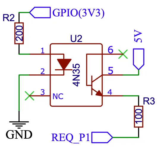
When using a type of MCU that provides 5V on the GPIO outputs instead of 3.3V, then use a 330 Ohm resistor instead of the 200 Ohm resistor.
Improving reader results
Section titled “Improving reader results”When telegrams are sometimes missed or when you get a lot of CRC errors, then you might have to do some changes to get better reader results.
It is recommended to set the rx_buffer_size option of the UART bus to at least the maximum telegram size,
which defaults to 1500 bytes. The default UART read buffer is quite small an can easily overflow, causing
bytes of data getting lost.
# Example configurationuart:  pin: D7  baud_rate: 115200  rx_buffer_size: 1700
dsmr:  max_telegram_length: 1700
It’s best when a hardware UART is used for reading the P1 data. Whether or not hardware UART is used can be checked in the config dump that you get when connecting to the API logger. Example logging output:
[02:38:37][C][uart.arduino_esp8266:095]: UART Bus:[02:38:37][C][uart.arduino_esp8266:097]: RX Pin: GPIO13[02:38:37][C][uart.arduino_esp8266:099]: RX Buffer Size: 1500[02:38:37][C][uart.arduino_esp8266:101]: Baud Rate: 115200 baud[02:38:37][C][uart.arduino_esp8266:102]: Data Bits: 8[02:38:37][C][uart.arduino_esp8266:103]: Parity: NONE[02:38:37][C][uart.arduino_esp8266:104]: Stop bits: 1[02:38:37][C][uart.arduino_esp8266:106]: Using hardware serial interface. ^^^^^^^^^^^^^^^^^^^^^^^^^^^^^^^^When using an ESP8266, then GPIO13 (e.g. pin D7 on a D1 Mini) can be used for hardware RX. However, to actually make it work, serial logging must be disabled to keep the hardware UART available for D7.
# Example configuration for ESP8266logger:  baud_rate: 0  level: DEBUG
uart:  pin: GPIO13  baud_rate: 115200
Bridging support / raw telegram logging
Section titled “Bridging support / raw telegram logging”You can use another uart to supply another P1 receiver with the same telegram. See configuration sample as used for bridging.
# define multiple uart'suart:  - id: p1_uart    rx_pin:      number: 4      inverted: true    baud_rate: 115200    rx_buffer_size: 1700  - id: p1_bridge_uart    tx_pin:      number: 10    baud_rate: 115200
# link input uart to dsmrdsmr:  uart_id: p1_uart  max_telegram_length: 1700
# log the telegram and pass telegram to p1_bridge_uarttext_sensor:  - platform: dsmr    telegram:      name: "telegram"      on_value:        then:          - lambda: |-              ESP_LOGV("dsmr", "telegram: %s", x.c_str());              p1_bridge_uart->write_str(x.c_str());