MCP2515
The MCP2515 communicates with ESPHome via the SPI bus; to use it, you must have at least one
SPI bus with both the mosi_pin and miso_pin defined in your ESPHome configuration.
The Wiring options section below illustrates how to wire up your MCP2515.
# Example configuration entry
canbus:
  - platform: mcp2515
    cs_pin: GPIOXX
    can_id: 4
    bit_rate: 50kbps
    on_frame:
    - can_id: 500
        then:
        - lambda: |-
            std::string b(x.begin(), x.end());
            ESP_LOGD("canid 500", "%s", &b[0] );
        - light.turn_off: light_1
    - can_id: 501
        then:
        - light.turn_on:
            id: light_1
            brightness: !lambda "return (x.size() > 0) ? (float) x[0]/255 : 0;"
ℹ️ Note
The MCP2515 only provides two receive buffers which are read once per loop cycle. This means, if more than two CAN frames arrive within a loop cycle (typically 16ms, possibly longer), frames are dropped.
This limitation makes the MCP2515 unsuitable for moderate- to high-speed CAN buses, especially automotive ones. Use the esp32_can component where possible.
Configuration variables

cs_pin (Required, Pin Schema): Is used to signal to a SPI device when it should listen for data on the SPI bus. Each SPI device has its own
CSline. Sometimes also calledSS.clock (Optional, frequency): The frequency of the clock crystal used on the MCP2515 device. One of
8MHZ,12MHz,16MHZor20MHZ. Defaults to8MHZ.mode (Optional, enum): Operating mode. One of:
NORMAL: Normal operation. (default)LOOPBACK: Loopback mode is useful for testing your connections to/from the device.LISTENONLY: Receive data only.
All other options from Canbus.
ℹ️ Note
Not all combinations of clock and bitrate are supported. An unsupported combination will not be flagged at compile time. Check your ESPHome device’s logs for a message like
Invalid frequency/bitrate combinationif you suspect this is an issue.
Wiring options
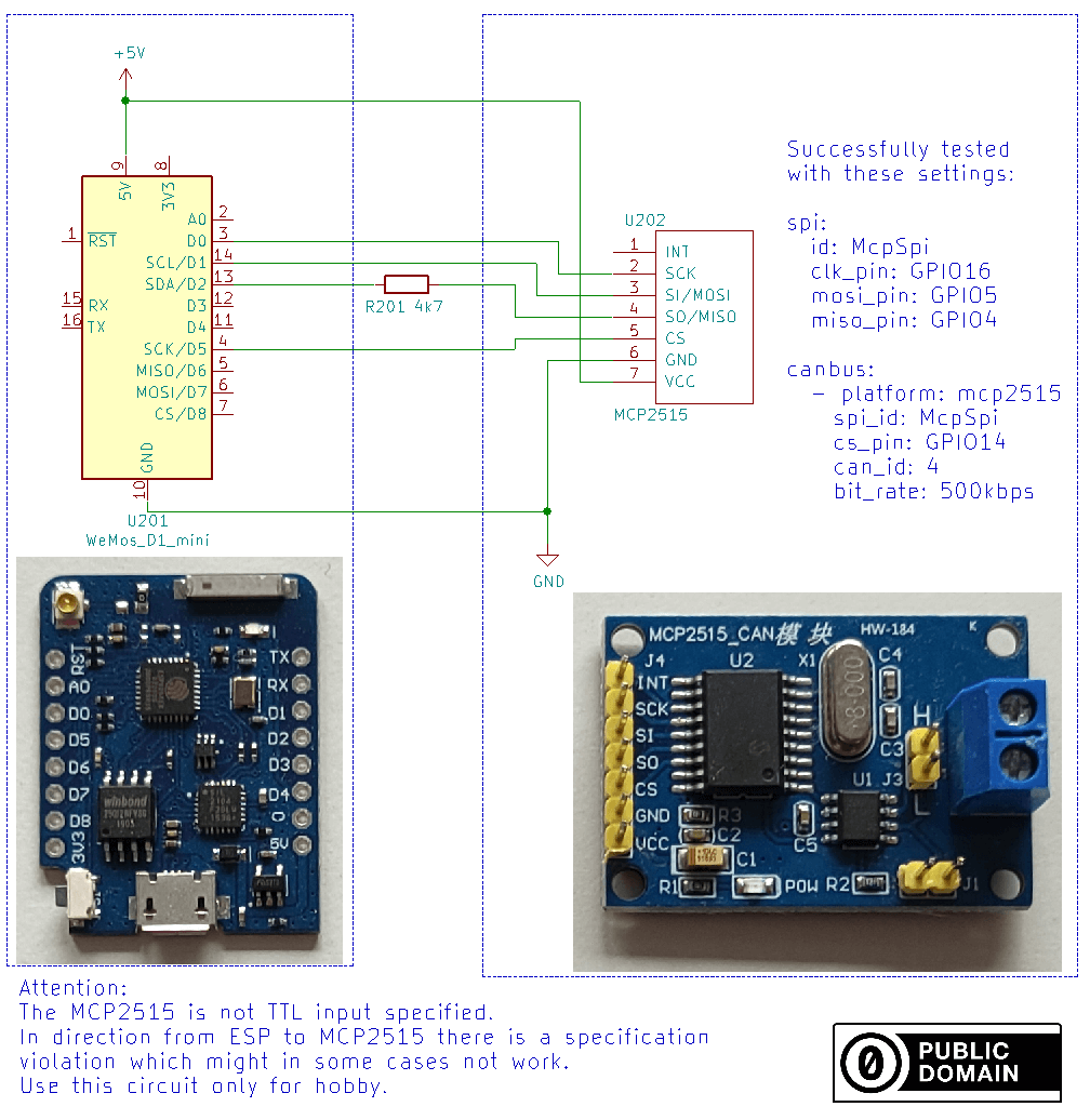
The easiest approach is to use fully assembled boards and just add one resistor on the MISO line. This runs MOSI, SCK and CS out of specification which is rarely a problem.
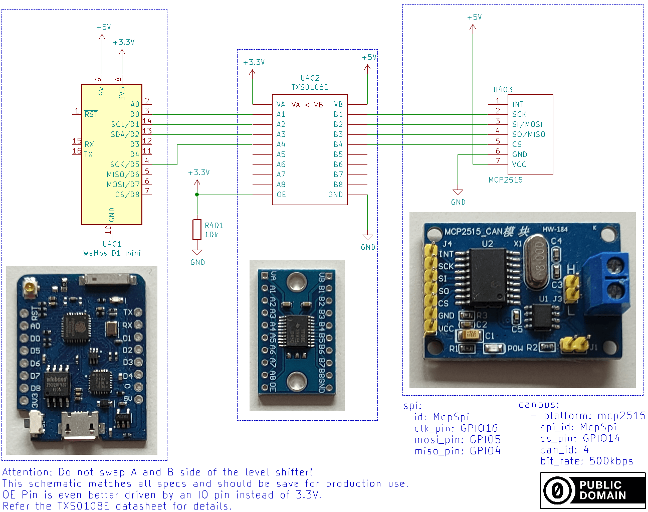
A more complex option is to properly convert the 3.3V and 5V logic levels with a level shifter.